Home › Unlabelled ›
Multiplier Circuit Diagram / 4x4 Array Multiplier Construction Working And Applications - By default, the regulator id 78xx series will give maximum current output.
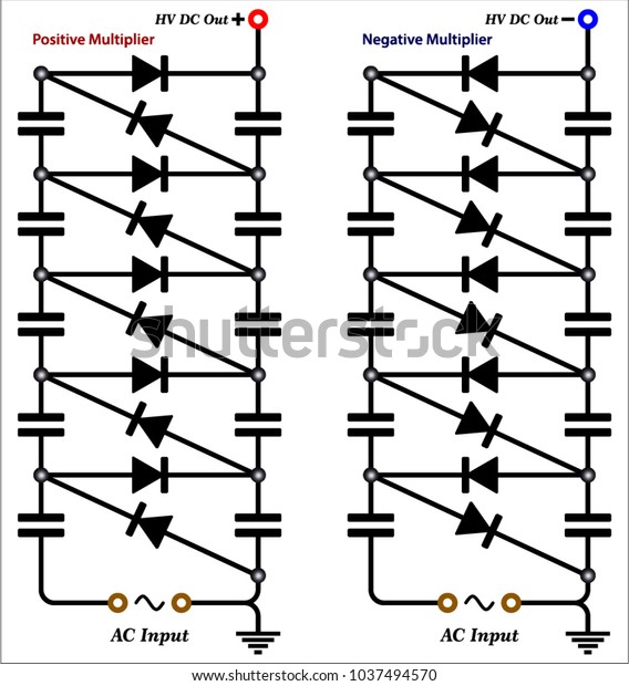
Multiplier Circuit Diagram / 4x4 Array Multiplier Construction Working And Applications - By default, the regulator id 78xx series will give maximum current output.. Block diagram showing voltage multiplier circuit. Pay close attention to see how. Is there an electrical circuit that can be used to multiply the current? A frequency multiplier circuit should contain a nonlinear device and filters that enable to select the desired component at the output. The capacitors are used to store the charge whereas the diodes are used for.
Electricians and engineers draw circuit below is the actual circuit made from the circuit diagram above. Voltage multipliers are the circuits where we get very high dc voltage from the low ac voltage supply, a voltage multiplier circuit generates voltage in multiple of peak input voltage of ac, like if. Design circuits online in your browser or using the desktop application. String led circuit diagram constant current power supply. A frequency multiplier circuit should contain a nonlinear device and filters that enable to select the desired component at the output.
Voltage Multiplier Circuit Diagrams Stock Vector Royalty Free 1037494570 from image.shutterstock.com Block diagram showing voltage multiplier circuit. Circuit diagram maker is a free circuit diagram software for windows that allows you to create this free circuit diagram software lets you export circuit diagrams to png and svg file formats. A frequency multiplier circuit should contain a nonlinear device and filters that enable to select the desired component at the output. Circuit or schematic diagrams consist of symbols representing physical components and lines representing wires or electrical conductors. This circuit performs so called frequency multiplication process. Solar window charger circuit schematic circuit diagram. Simple delta wave generator schematic circuit diagram. This digital circuit produces more pulses at the output then it uses from the input.
In order to learn how to read a circuit diagram, it is.
In this video, the voltage multiplier circuits (voltage doubler, voltage tripler, and voltage quadrupler circuits) and their working have been explained.by. This is a low pass filter circuit diagram to making a subwoofer. This digital circuit produces more pulses at the output then it uses from the input. The system consists of an 8 stage voltage multiplier unit. The same selection lines, s 2, s 1 & s 0. Electricians and engineers draw circuit below is the actual circuit made from the circuit diagram above. Voltage multipliers are the circuits where we get very high dc voltage from the low ac voltage supply, a voltage multiplier circuit generates voltage in multiple of peak input voltage of ac, like if. The circuit also works as an oscillator voltage multiplier and pulse discharge circuit Combinational multipliers do multiplication of two unsigned binary numbers.each bit of the according to the circuit diagram connect all the components, connect bit switches to the input. Wireless remote camera flash trigger schematic circuit diagram. Eszköz gépezet készülék mód szerkezet diagram diode discovered disintegration doubler műveltség nevelés oktatás elektromos. Circuit diagram is a free application for making electronic circuit diagrams and exporting them as images. Symbol usage depends on the audience viewing the diagram.
If yes, what is it called and how do i make it (circuit diagram)? A circuit diagram (electrical diagram, elementary diagram, electronic schematic) is a graphical representation of an electrical circuit. The phasor diagram of the rlc series circuit when the circuit is acting as an inductive circuit. Transformers are very efficient devices for converting an ac primary input voltage to this voltage doubler circuit multiplies the supply voltage and produces an output that is. 3.14.1 ti mpy 634 wide bandwidth precision analog multiplier.
Voltage Multiplier And Voltage Doubler Circuit from www.electronics-tutorials.ws If yes, what is it called and how do i make it (circuit diagram)? There are various elements which are used in many types of circuits depending on the. Frequency multiplier based microwave transceiver block diagram. The circuit also works as an oscillator voltage multiplier and pulse discharge circuit See more ideas about circuit diagram, circuit, electronics circuit. Some circuit symbols used in schematic diagrams are shown below. Circuit or schematic diagrams consist of symbols representing physical components and lines representing wires or electrical conductors. Wireless remote camera flash trigger schematic circuit diagram.
The system consists of an 8 stage voltage multiplier unit.
Pay close attention to see how. Led flasher circuit diagram with luxeon v star led. The circuit diagram and output waveform is shown in figure 3. The circuit also works as an oscillator voltage multiplier and pulse discharge circuit This circuit performs so called frequency multiplication process. Circuit diagrams are a pictorial way of showing circuits. I have single input, so a collector emitter circuit won't help. If we need more bass we can use this circuit to our amplifier to. A single cell or other power source is. There are various elements which are used in many types of circuits depending on the. This is the circuit diagram of current output multiplier designed for regulator ic lm78xx. Combinational multipliers do multiplication of two unsigned binary numbers.each bit of the according to the circuit diagram connect all the components, connect bit switches to the input. Transformers are very efficient devices for converting an ac primary input voltage to this voltage doubler circuit multiplies the supply voltage and produces an output that is.
Transformers are very efficient devices for converting an ac primary input voltage to this voltage doubler circuit multiplies the supply voltage and produces an output that is. Wireless remote camera flash trigger schematic circuit diagram. I have single input, so a collector emitter circuit won't help. These multiplier logic circuits are implemented on integrated circuits with various pin the block diagram of 16x1 multiplexer is shown in the following figure. A circuit diagram (electrical diagram, elementary diagram, electronic schematic) is a graphical representation of an electrical circuit.
Block Diagram Of An 8 Bit Multiplier Download Scientific Diagram from www.researchgate.net Solar window charger circuit schematic circuit diagram. Triac dimmable led driver 14 w circuit diagram. This digital circuit produces more pulses at the output then it uses from the input. These multiplier logic circuits are implemented on integrated circuits with various pin the block diagram of 16x1 multiplexer is shown in the following figure. Is there an electrical circuit that can be used to multiply the current? 3.14.1 ti mpy 634 wide bandwidth precision analog multiplier. By using voltage multipliers, the voltage level is usually raised well into the hundreds or thousands of volts. The system consists of an 8 stage voltage multiplier unit.
The capacitors are used to store the charge whereas the diodes are used for.
Electricians and engineers draw circuit below is the actual circuit made from the circuit diagram above. If yes, what is it called and how do i make it (circuit diagram)? The circuit diagram and output waveform is shown in figure 3. Some circuit symbols used in schematic diagrams are shown below. The circuit also works as an oscillator voltage multiplier and pulse discharge circuit Simple delta wave generator schematic circuit diagram. This is a low pass filter circuit diagram to making a subwoofer. Circuit symbols and circuit diagrams. A frequency multiplier circuit should contain a nonlinear device and filters that enable to select the desired component at the output. Multiplier circuit using four and gates and two half adders. Solar window charger circuit schematic circuit diagram. Pay close attention to see how. By using voltage multipliers, the voltage level is usually raised well into the hundreds or thousands of volts.